


DIY Studio Skills: Make & Repair Your Own XLR and TRS Cables
Want to save yourself some money, have the satisfaction of knowing exactly how good your cables really are, and have some fun too? If you enjoy DIY projects, you can easily build and troubleshoot audio cables for yourself. The process is relatively simple, requires no expensive tools, employs easy-to-acquire soldering skills and you need only the most basic knowledge of electrical circuits.
Mastering this essential audio skill means no more wasting money by throwing away busted cables, no more wasting time by making last-minute trips to the music store or waiting for online orders to arrive before you can get back to work, and no more compromising by using cables that are too long, too short, or too junky for your needs.
The act of soldering connections is an art, but it is one that is relatively easy to master if you keep in mind a simple set of principles in mind, and follow the same steps each time. So today, we’ll give you a clear and comprehensive step-by-step process, and show you what it takes to start building and repairing your own audio cables.
Read on below for all you need to know finally get started repairing and building cables for yourself.
Tools of the Trade: Testers
If you are going to start building and repairing cables, it helps to know whether or not your cables are working, and where any issues with them may lie.
-

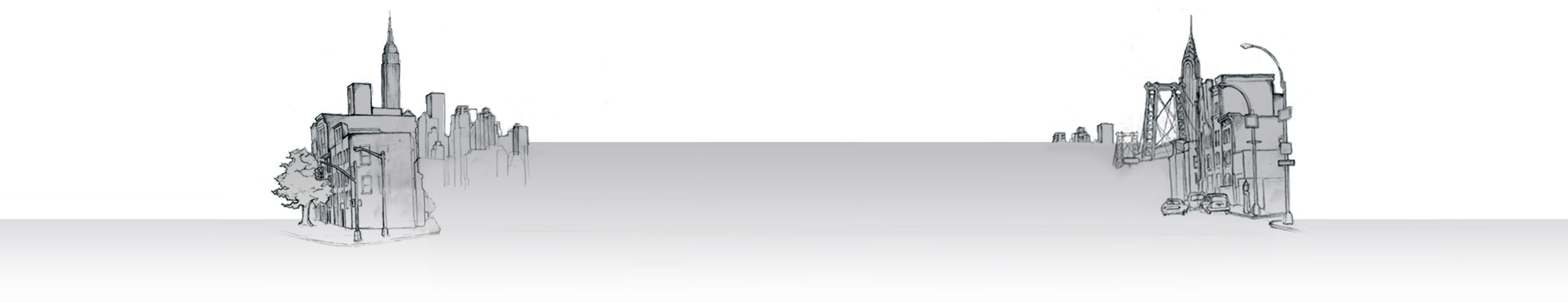
- A continuity tester.
-

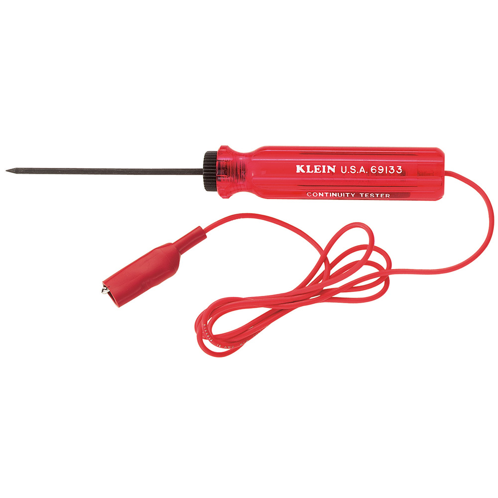
- A multimeter.
-
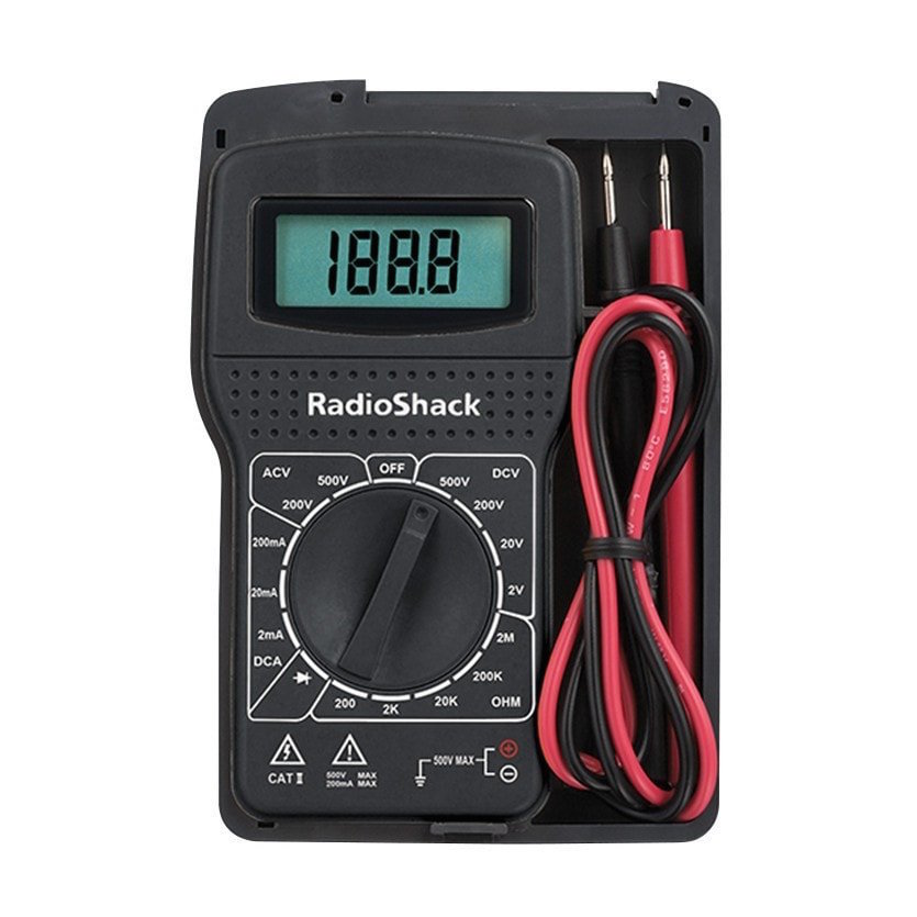
- A cable tester.
The least expensive option for testing your cables is a “Continuity Tester”. I bought mine years ago for less than a dollar, and they routinely sell new for just a few dollars today. A continuity tester has only one use: It will tell you whether your cable is capable of making a circuit. For troubleshooting and building audio cables, that is all we really need.
The next step up from here is a “Multimeter”. I bought one similar to the model pictured above for barely more than $5.00 several years ago. Comparable models can often be found new for around $20 or less today. I own more expensive meters, but this one fits in my pocket and if it disappears (or if I break it) it doesn’t cost much to replace.
Using a multimeter to test continuity simply requires switching to the ohms (resistance) setting on the meter and testing each pin, of the cable end-to-end on your connector for continuity. If a connection is good, it should read read “0 ohms” on the meter, showing that the signal is flowing with no resistance. In addition to measuring the resistance of a cable, a multi-Meter gives you the capability to measure voltage (in AC and DC), current, and sometimes more.
Your third option, which is the most expensive—and the most convenient—is a “Cable Tester”. I have seen some new models go for as little as $20-$30. Using one of these simply requires plugging the suspect cable into two of the available jacks on the device. Many models can even tell you at a glance which pins are passing signal properly and which aren’t. Typically, you’ll find plugs of a variety of types—1/4” TS, TRS, XLR, RCA, Speakon, Banana, even DIN and Network Rj45 or more esoteric types.
Tools of the Trade: Soldering Equipment
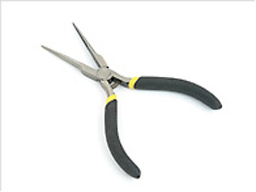
In addition to at least one of these testing devices, a good pair of needle nose pliers and a small screwdriver set are two essential tools for building or repairing cables. If you want to get even fancier, some people like having their work pieces held firmly in place with small vise, which acts as an additional hand, making the soldering job easier.
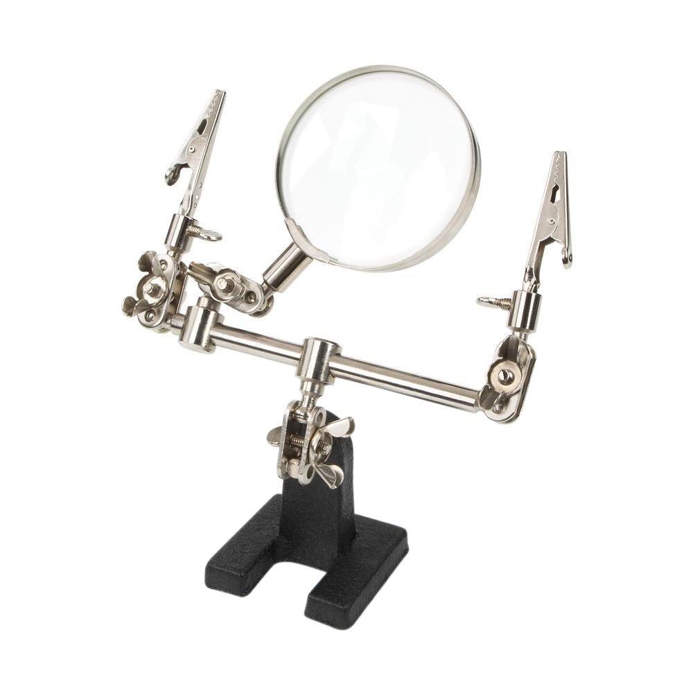
A “Helping Hand” tool—basically a pair of alligator clamps fixed to a solid base—is another inexpensive option that can help make the process easier, though not quite a sturdy as a good table-mounted vise grip.
Of course, you’ll also need a Soldering Iron, preferably with a good base to rest it on. The most common soldering jobs are best performed with a simple, low powered 25-40 watt soldering iron, which helps ensure that your soldering joint never gets overheated.
-
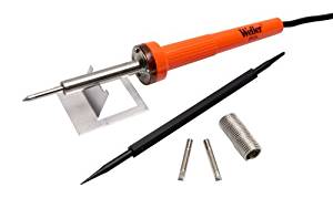
- A soldering iron with base.
-
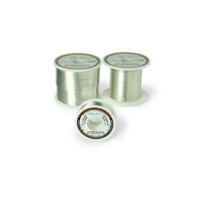
- Silver solder.

-
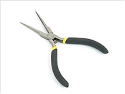
- Needle nose pliers.
-
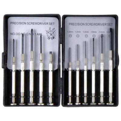
- A screwdriver set.

-
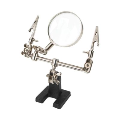
- A helping hand tool.
-
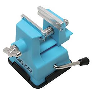
- A vise grip (optional.)
Some people prefer using soldering guns, which are trigger controlled and operate at much higher wattages, usually 100 watts and 140 watts. Higher wattage means you can heat your solder much more quickly, but it is much harder to control.
I do not recommend that beginners using a soldering gun, as the risk of destroying the wire and the connection is that much greater. (In addition, there is the higher risk of getting burned in the process.)
Lastly, you’ll need a set of wire strippers or a razor blade to remove the out layers of your cabling, and a good spool of Silver Solder for making your connections.
For safety, it is advisable to wear some eye protection, work in a well-ventilated area, and consider trying a face mask if you’re worried about fumes. If you have very long hair, you’ll want to make sure it is tied up and tucked away.
With a little common sense, the process is very safe, simple and easy to learn.
CAUTIONARY NOTE: Always unplug the cable first. Never work on a cable that is still plugged into anything, or that may have power running through it.
Troubleshooting and Repairing Cables
The most common way to discover a bad cable is in use, when you notice an issue with noise or lack of signal.
If you’re on the job and have identified the source of the problem as being the cable, you should immediately remove it from service, replace it and move on.
So that you don’t mistakenly grab this broken cable again, it helps to label it. Simply grabbing a piece of console tape and a black marker will do the trick. Some audio engineers will label a cable “NFG”, which stands for… “No Good”. (Or something to that effect.)
When you’re done with your session, and you have a chance to go back and take a look at the source of the problem, here are some basic steps to follow to diagnose the issue and then fix it:
Step 1: Check for Physical Problems
Is the cable itself kinked or frayed? Is the cable’s jacket split or squashed? Are the connectors securely fastened to the cable? Are they bent? Are they corroded?
Take the removable covers off your connectors and look for frayed or partial connections. Look for any abnormal physical change. Corrosion is rare and can be remedied. Some wear is unavoidable, but it should be minimal.
Step 2: Check the Conductivity of the Cable
Testing a cable for conductivity can be done using a cable tester, a multi-meter, or a continuity tester. A simple end-to-end test with the test tool is all that is needed to determine good or bad. Make sure to test one connection point at a time if you’re using a multi-meter or continuity tester.
1/4″ TS connectors, like the kind used as instrument and speaker cable have only two connection points on each side ( the “tip” and “sleeve”), while TRS and XLR cables have three connections labeled 1, 2 and 3.
For a TS cable, make sure that signal from the tip of one cable gets to the tip of the cable on the other side, and that signal from the ring gets to the ring on the other side. The same idea applies to each of the numbered pins on TRS and XLR cables.
Ninety-nine times out of a hundred, this is where you’ll find your problem: Either you’ll discover that a soldered connection will be broken, or you’ll find that the cable was mis-wired in some way, with pin 2 on one end corresponding to pin 1 on the other end of the cable, or something similar.
If you find that signal does pass through from one connector to the other properly, try flexing the cable along its length while the tester is connected to see if the problem is a breakage within the cable itself. This is more rare failure point, and you’ll often see some obvious damage or crimping somewhere along the cable’s length.
Step 3: Decide to Replace or Repair Depending on Condition
If there are too many issues with the cable or connector, I always replace them, and I recommend that you do the same.
I don’t throw them away, but rather cut or otherwise divvy them up into useable component parts. A long cable with a bad crimp somewhere along its length will often turn into two good cables, that can last many more years. A partially damaged connector will often have perfectly good parts that can be used to repair another partially damaged connector.
If the cable is too far gone, or if you are unable to salvage as much length as you need, you may want to replace the cable altogether by building a new one from scratch.
Step 4: Repair or Build Your Cable
If the problem is a bad connector, cut it off and replace it by soldering in a new replacement. (We’ll go into some more detail on developing your soldering skills in a moment. )
If there is a problem with the cable itself, cut the cable at the problem site, and replace the plug. You’ll often be able to re-use the connector.
If you’re ready to scrap the whole cable, all you need is some new cable, a pair of connectors, your soldering kit, and a few minutes of time.
Either way, you’ll need to know the basics about connector types, cable types and how to get started soldering.
Selecting Your Connectors
-
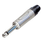
- A TS or “tip-sleeve” connector.
-
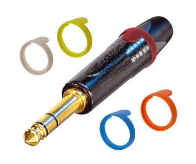
- A TRS connector. (Note the third contact point, called the “ring”).

-
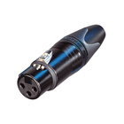
- A female XLR connector.
Select the proper connectors for the cable type. TRS for balanced TRS equipment connections and professional studio patching. TS for high impedance instrument and amplifier applications. XLR male and female for microphone cables and some patching situations.
Prices are so competitive today that you may as well buy the best. Two solid names are Neutrik and Switchcraft, and they can be had for as little as $2-$3 each.
REPLACEMENT PARTS
Selecting Your Cable
-

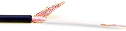
- A two-conductor wire for TS type connectors. Note that the underlying conductor has been exposed so it is ready for soldering.
-

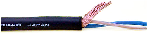
- A three-conductor cable used for XLR and TRS-style connectors.
-
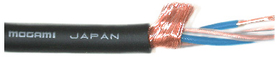
- For especially long or critical cable runs, some prefer “quad” cable, which uses two conductors for the pins that carry signal.
Since you are building an audio connection cable, don’t skimp. If there is one very reliable top-shelf name and that is Mogami. I have purchased excellent quality cable made by them for as little as $.50 to $.75 per foot. For the studio, it’s hard to beat the look, feel and ease of coiling you’ll get from Mogami.
Another major name in this field is Canare, which makes very strong, robust cables, and may be preferable for live use or in applications where you expect a lot more wear and tear. A 20 foot balanced microphone cable can be made for around $14.00 versus a store bought one can cost $50.00 or more.
Making Connections
Now that you’re ready to build or replace your cable, here’s all there is to it:
Step 1: Strip the Wire and Clean the Connection Points
The first step in making a solid connection is stripping the wires and/or cleaning the connection points.
To strip the outer layer of the cable and reveal the shield and internal conductors, you can use a basic razor blade or a pair of wire strippers.

Closeup of a two-conductor wire for TS type connectors. Note that the underlying conductors have been exposed so it is ready for soldering.
Wire strippers are safer to use if you have little experience, but with a little practice and a gentle touch, a handy razor blade can be even quicker, cheaper, and gentler on the cable too. Just roll the cable back and forth across the blade to make a shallow incision, and then pull off the rubber end.
You can find wire strippers built for the gauge of cable you’re working with. The nicer ones are adjustable. Be careful of putting your wire-strippers on two small of a setting, as you may accidentally cut the cable instead of just stripping it.
You’ll want to strip a small amount of the outer rubber coating off if the ends of the conductors, typically, about a half an inch.
In most applications, one of the “wires” you’ll be soldering to the connector is actually the thin metal shield that you’ll find protection the interior cables. To make this cylindrical metal shield into a usable wire, simply make a lengthwise incision with some wire cutters (or sometime even by tearing it with your fingers) and then roll it into a wire-like shape by hand. You’ll solder the shield to pin 1 on an XLR cable or to the long “sleeve” on a TS or TRS cable.
If you’re working with a used connector, and there is already piece of wire soldered to it, simply heat up the connection point with your soldering iron and remove the wire by gently tapping it on an expendable solid surface, or pull it free with a pair of needle nose pliers. If necessary, brush the connection with a small wire brush to remove any foreign debris.
Step 3: ”Tinning” the Connection Points
The second step in making a solid connection is called ”Tinning”. This means coating all the connection points with a small layer of solder—both the stripped wire ends and the plug contacts as well as the tip of your iron—before you get started join your cable and connector together. Tinning the parts first makes soldering a solid connection much quicker and easier.
To do this, pre-heat your soldering iron, and as it warms up, test it by melting a small amount of solder on the tip, thereby tinning your iron. Once you are able to do that, the iron is ready to use.
Next, lay your connector and cable ends on a solid, expendable surface (a scrap piece of plywood or a soldering mat for example). Heat the connection point (or wire) with the tip of the soldering iron and melt the solder onto the point without touching the solder to the iron tip.
This is the counter-intuitive part of the soldering process for beginners, so it bears repeating: You don’t want to heat your solder directly with the soldering iron. Instead, you want to heat the part using your soldering iron, and simply “allow” the solder to melt onto the heated part.
Your motto from here on out is “Heat the part, not the solder.”
Step 3: Mechanical Attachment
The third step in making a solid mechanical connection.
Where possible, that means placing a tinned wire through eye of the connection point on your plug and folding it over, squeezing it tight. This not only helps the wire stay in place as you start soldering, but can also help reduce some of the stress load on the soldered connection when the cable is in use..
If there is no hole to thread the wire through, an alligator clamp can help the wire stay in place until you’re done soldering.
At this stage, make sure you have the right wire attached to the right connection point. You’ll want to solder the outer shield to pin 1 on an XLR or to the sleeve on a TRS or TS cable. For your other connection points, just make sure that you’re using the same color wire in the same slot on each connector.
You also want to be sure that all the parts you need to seal your connector when you’re done are already on the cable before you get soldering.
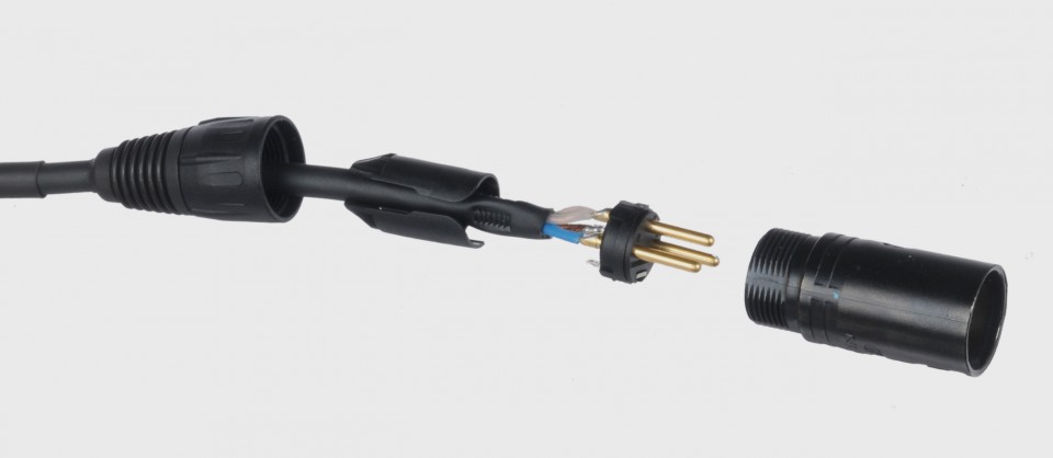
Make sure that all the rear parts of your connector are on the cable before soldering.
Step 4: Soldering the Connection
Now that you have your parts tinned and your wire threaded or clamped into the connector, the fourth and final step is to actually solder the connection.
Take your time and be sure to let the soldering iron come up to temperature before starting to solder.
Once again, the idea is to heat the connection point with the tip of the soldering iron, and melt the solder onto the connection point without the solder touching the iron tip directly. Remember: Heat the part, not the solder. Once you’ve let the solder melt over the connection point and then cool, you have finished joining the connector and wire.
Make sure you you have soldered your wire securely by giving it a firm little tug and bending the cable gently. Then, test the integrity of the connection using your cable tester, multimeter or continuity tester.
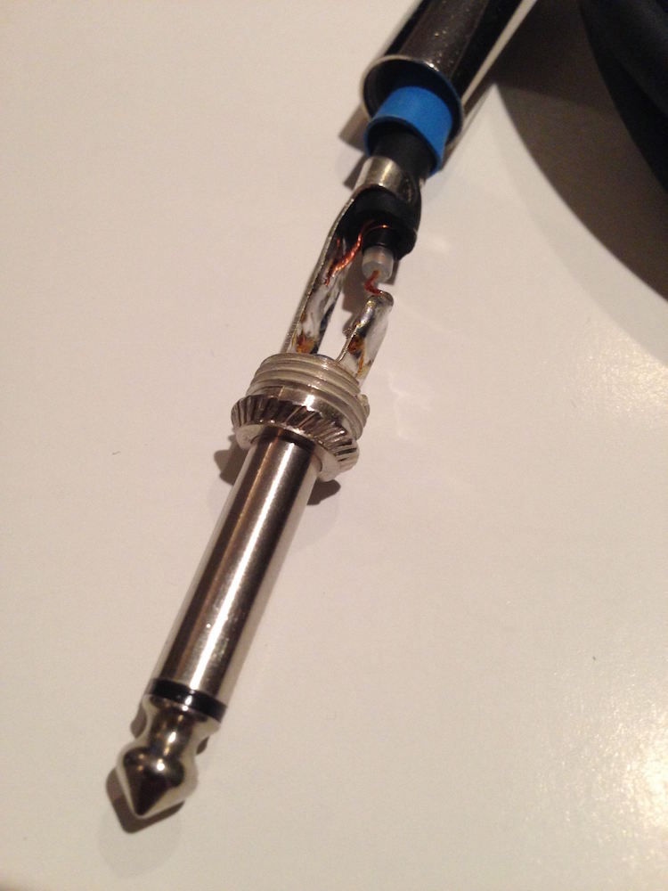
-

- A completed TS connection.
-
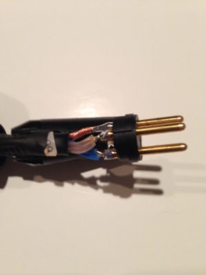
- A completed XLR Male connection.
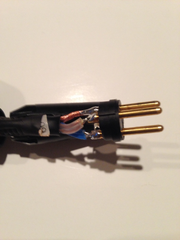
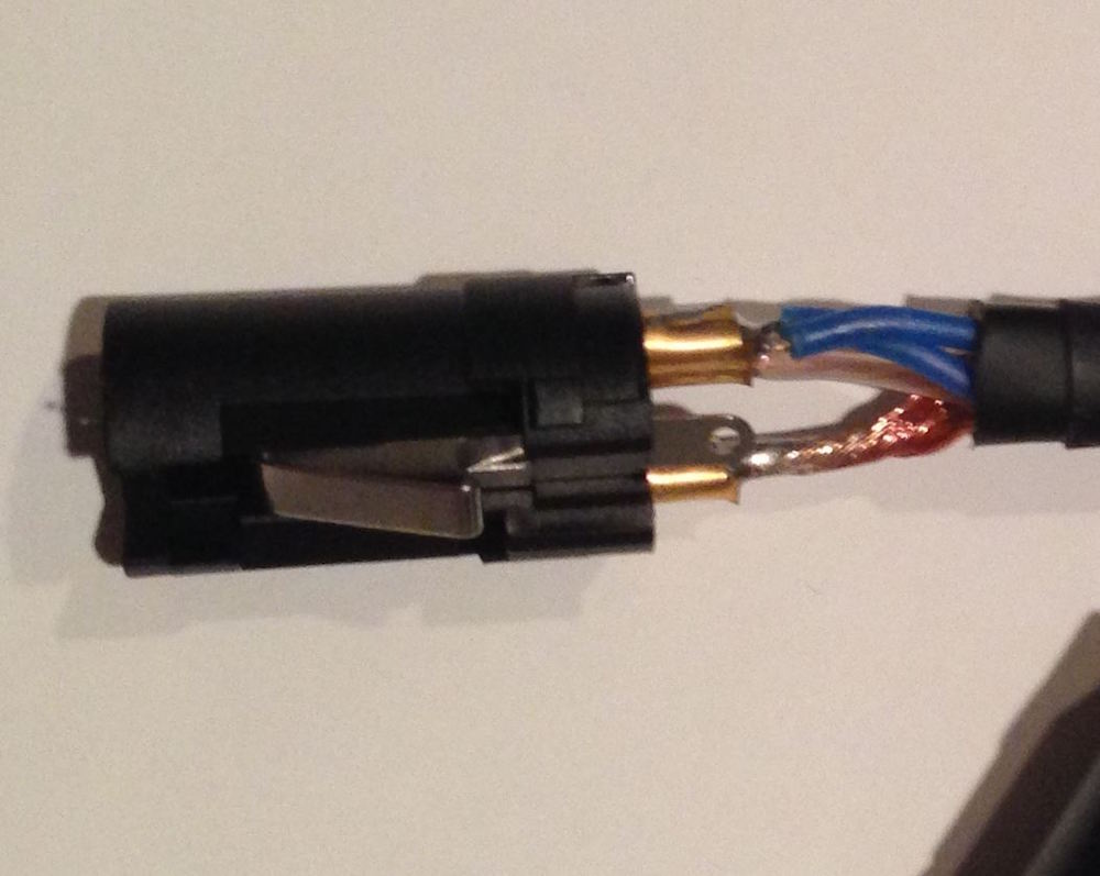
-

- A completed XLR Female connection.
CAUTION:
The process of soldering should not be taken lightly.
Although you shouldn’t have to worry about lead fumes at these temperatures (or with many types modern types of solder) there can still be some fumes that you may react to, so any soldering should be done in a well-ventilated area.
Soldering also requires quite a bit of heat: Enough heat to cause burns to skin or hair and to put holes in clothing if you’re not careful.
The soldering iron, the solder and the connection being soldered all have to get physically very hot (generally somewhere from 575 to 700 degrees Fahrenheit) so you’ll want to be careful to avoid touching the connector and the wire as well as the metal parts of the soldering iron.
It should go without saying, but be sure you’ve turned off your soldering iron when done.
Summing it Up
Moving up to building and repairing your own cables is an easy, enjoyable and satisfying process. Whenever you patch in a cable, you’ll be able to say “I built that”, and when one goes bust, you’ll know how to make it work again at minimal cost.
As you build your skills here, you may find your confidence grow, and eventually find yourself thinking about taking on more elaborate DIY projects in the future, saving yourself money as you improve you sounds.
For now, have fun soldering, enjoy your accomplishments, save yourself some money, and be safe.
Rob Dominiak is a musician, writer and engineer who lives in Upstate New York.
Please note: When you buy products through links on this page, we may earn an affiliate commission.
charlie
March 2, 2017 at 4:44 pm (7 years ago)This is a good article but as someone who’s been doing this a long time, I feel there are some missing details. Using a multimeter to measure resistance is my last choice since most VOMs have a diode check mode. This provides an audible beep for continuity, more convenient than waiting for a digital VOM to auto-scale until it hits zero, for instance.
When testing your cables, check continuity from pin 1 to pin 1, but also always check pin 1 to the other pins to ensure there aren’t any shorts. One proud engineer once soldered up a special mic stand that had a solid metal piece which shorted all three pins of the connector. The handy cable tester gave him green lights. However when phantom power was applied to the mic preamp, all of the special blue smoke inside was released! (I swear that engineer wasn’t me. I did notice the smoke coming from the now-fried remote mic pre, however).
Labeling bad cables is fine, but taping over an end or (better yet) cutting off the end with a knife or pliers is an easier way to make sure no one will try to use that cable again until it is fixed. Tape can get sticky, and sticky cables don’t make for fun cables.
I’m glad you mentioned “…be sure that all the parts you need to seal your connector when you’re done are already on the cable before you get soldering.” If you haven’t yet soldered on a connector forgetting to install the other parts, don’t worry, you will. I speak from experience!
Strangebone
March 3, 2017 at 1:09 am (7 years ago)I would please like to also include Belden as a superior cable. It is actually made in the U.S.A. and has been an industry standard long before the Japanese entered the market. It is far easier to strip than Mogami, which uses PEX as the inner conductor’s insulation and in my experience is somewhat of a pain to deal with. I am a humble audio engineer and in no way affiliated with the brand I support.
ashcat_lt
March 4, 2017 at 1:32 pm (7 years ago)Most of the time you can just rip a bad connector off with your hands. It’s a great way to work off the frustration that usually comes from trying to diagnose a bad cable. 😉 This is not the best idea for an AC mains cable, or at least you should make sure to remove the plug rather than the socket end.